
The signal-to-noise ratio quantities the observability of an output signal. This implies the existence of a basic limit below which signals are no longer distinguishable. Electrical noise may persist even after the input signal has been removed from the electronic circuit.

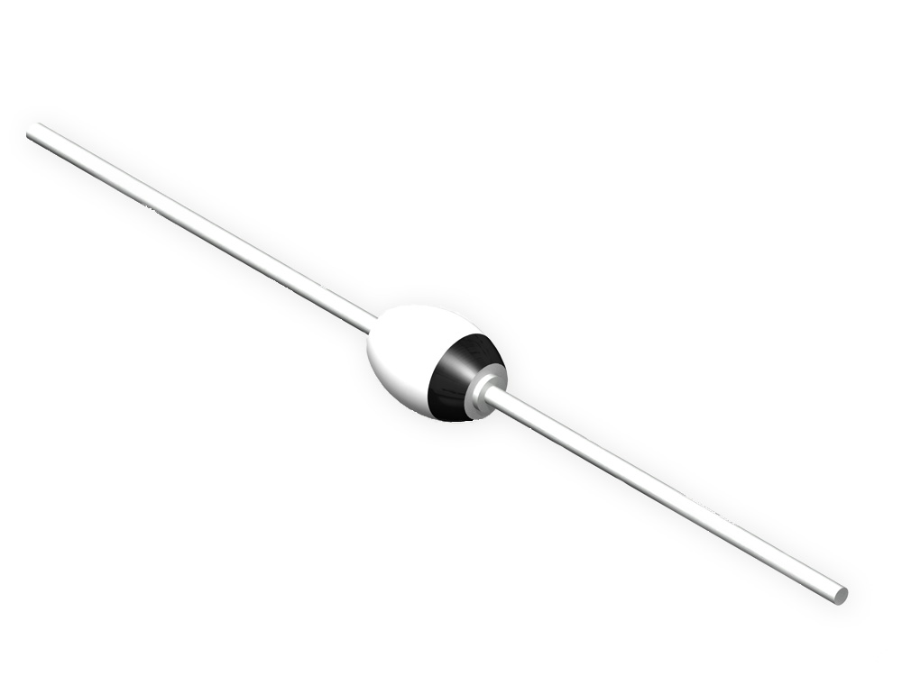
Perhaps a discussion of the various types of electrical noise giving rise to degradation of the observed signal, would be in order. But the root mean square of the fluctuation is measurable. The average of these fluctuations are zero, due to their randomness. Noise causes the signal to fluctuate around a given value. Shot noise in a diode is the random fluctuation in a diode current, I, due to the discrete nature of electronic charge. This is caused by a random fluctuation of voltage and current or electromagnetic fields.

We know that the minimum signal observable in an electronic circuit is set by the level of electrical noise in the system. Therefore, plate current is smaller than emission current, or the cathode produces more electrons than the anode can. At a constant filament voltage, a dynamic equilibrium sets in, so that the number of electrons reaching the plate and the number falling back to the cathode is equal to the number of electrons emitted by the cathode. Accordingly, the retarding field region (from 0 to x min) contains not only electrons traveling away from the cathode, but also those falling back toward the cathode. It will slow down to a stop, and the field will push it back to the cathode. If the electron is below this value, the electron will not be able to overcome the potential barrier. Thus, there is a high retarding electric field near the cathode ( 0 2 e m V min. The density of the electron cloud near the cathode increases to the point where it forms a negative potential region whose minimum, V min, is usually within a few hundredth or tenths of a millimeter of the cathode surface. Electrons having low initial velocities are driven back to the cathode by the negative space charge due to the electrons. As the filament voltage is increased, emission increases, and so does the space charge. This region is known as the emission-limited region. One could say the all electrons are being sucked away from the cathode by the anode. In this case, the plate current equals the emission current. The vector of the electric field is directed from the plate to the cathode, so all the electrons escaping from the cathode make for the plate. Since the electrons making up the space charge are negative, the potential in the cathode-plate space goes up, though all points remain at positive potential. This charge alters the potential distribution. When the filament voltage rises, the electrons leaving the cathode gang up in the interelectrode space as a cloud called a space charge. In this case, the potential distribution in the cathode-plate space is represented by a straight line which joins the points corresponding to cathode potential V k = 0 and the plate potential V p. If V f = 0 (no filament voltage) then no emission takes place, the diode may be regarded as a parallel-plate capacitor whose potential difference is V p.

The space between the anode and the cathode is evacuated, so that electrons may move between the electrodes unimpeded by collisions with gas molecules. When the anode is negative with respect to the cathode, electrons are repelled by the anode and the reverse current is almost zero (due to the tail of the Maxwellian distribution of the electrons it is greater than zero). Electrons moving from the cathode to the anode constitute a current they do so when the anode is positive with respect to the cathode. At sufficiently high temperatures electrons are emitted from the cathode and are attracted to the positive anode. The vacuum diode consists of a hot cathode surrounded by a metal anode inside an evacuated enclosure. Eugene Dulov, in Kinetic Boltzmann, Vlasov and Related Equations, 2011 14.2 Description of Vacuum Diode


 0 kommentar(er)
